The project
Lithium iron phosphate batteries work best between about 25 and 45 °C. Above that they lose performance, discharge faster and wear out sooner, and the heat comes from inside the cells, so it has to be pulled out. Most battery cooling systems use a refrigeration cycle or a water loop, which needs pumps or compressors, takes up space and needs regular maintenance.
This project replaces them with thermoelectric coolers (TECs), solid-state modules that pump heat from one face to the other when current flows through them. The cold face sits against the battery, and the hot face is carried away by heat sinks, a heat pipe and a fan. There are no moving parts in the cooling itself, and the whole system is compact. It was the final year design project of a team of four at GIKI.
My part
I did the mathematical modelling of the cooling system, and I worked on the fabrication of the prototype. I also assisted with the electronics. The four of us built everything from scratch, from the frame to the wiring, and the COMSOL simulations were the team's way of checking the model before we built.
The design
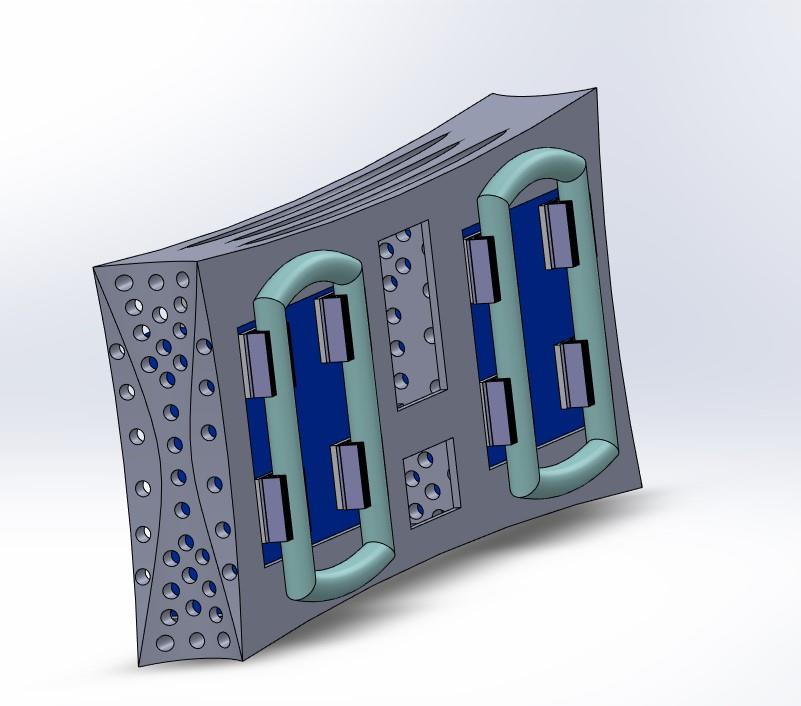
The batteries sit in a lightweight aluminium frame with four TECs behind each one. The cold side of each TEC faces the battery, with thermal paste between them to improve conduction. The hot side is attached to a heat sink. The plan for carrying the heat further was a sealed pipe of cooling gas that expands upwards when heated and is cooled again by a fan, so the flow works on gravity alone.
The electronics decide when the cooling runs. Two batteries are in use at a time, and temperature sensors on each battery feed a microcontroller. When one battery gets hot, the TECs run for a few seconds. If it keeps heating, that battery is switched off and a third one takes over, so no battery is ever left to overheat.
TECs draw a lot of current when run on their own. To cut the power needed, they are wired in two series rows, and the two rows are connected in parallel. That keeps the cooling output while lowering the input current.
The model I built
I started from the energy balance of one TEC. The heat it can pull from the cold side is the Peltier heat pumped across the module, minus half the Joule heat generated inside it, minus the heat that conducts back from the hot side. Half of the Joule heat is used because it splits equally between the two faces.
Qc = α·I·Tc − 0.5·I²·R − k·ΔT
Here α is the Seebeck coefficient, I the current, Tc the cold side temperature, R the electrical resistance, k the thermal conductance and ΔT the difference between the hot and cold sides. The model shows that the TEC stops cooling once the Peltier heat is used up by conduction and half the Joule heat. The electrical power the TEC consumes is I²R + αIΔT, so the coefficient of performance (COP) is the cooling capacity divided by that power.
The rest of the heat path was modelled the same way. The heat sink is described by its fin efficiency and total surface area, the heat pipe by an overall heat transfer coefficient, and the fan by the natural convection airflow set up by the temperature difference. The aim was to maximise the cooling capacity and keep the electrical power as low as possible, which means a high COP for the whole system.
Simulation
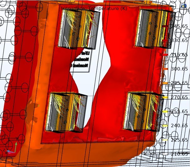
The team checked the design in COMSOL Multiphysics 5.6 with a stationary heat transfer study of the frame, batteries, TECs and heat sinks. The batteries were set to 50 °C, the heat sinks to room temperature, and each TEC had a cold face at −10 °C and a hot face at 60 °C. The result showed the heat leaving the battery mainly through the area under the TECs, which brought the battery surface down to a normal operating temperature, while the centre and upper part of the battery saw little heat transfer.
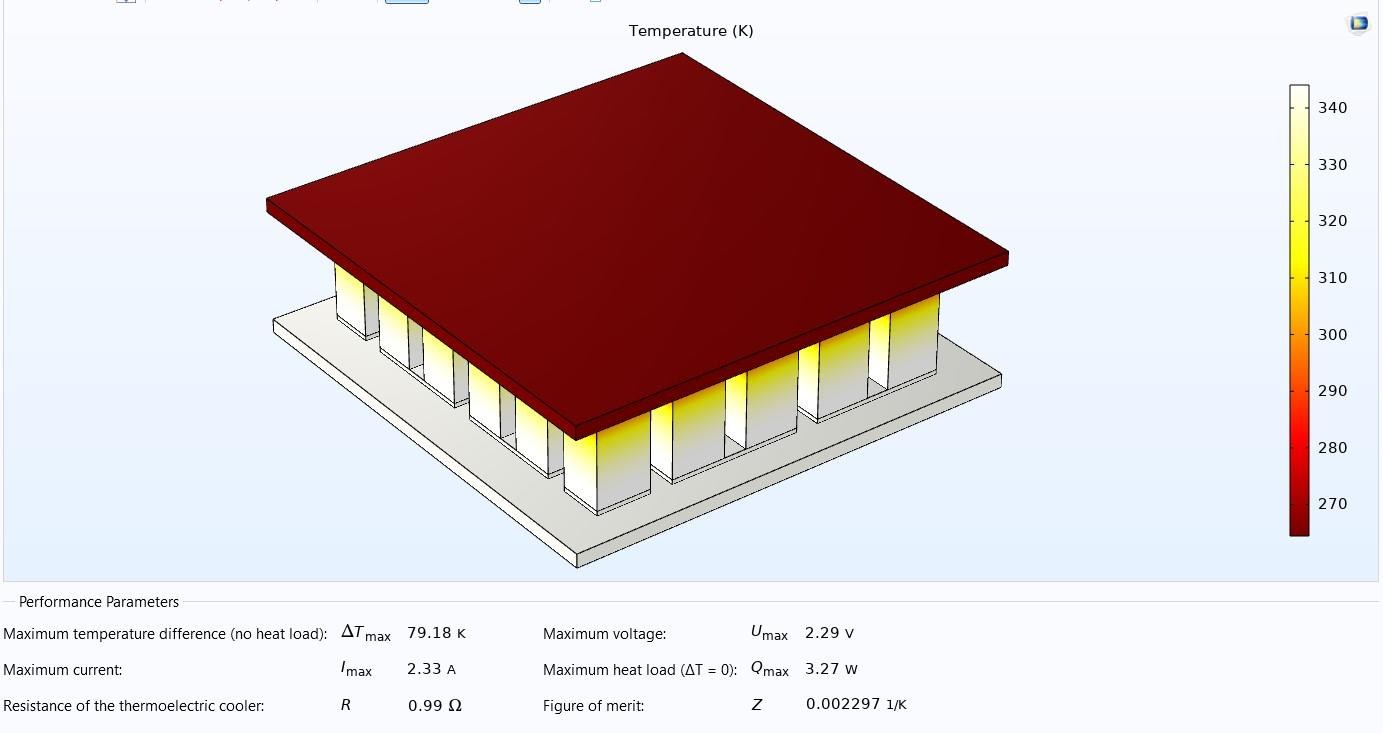
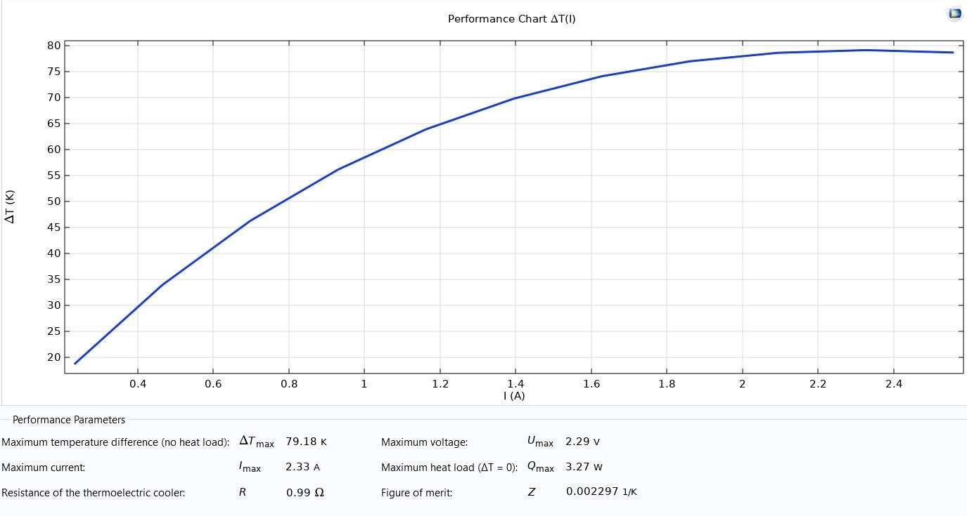
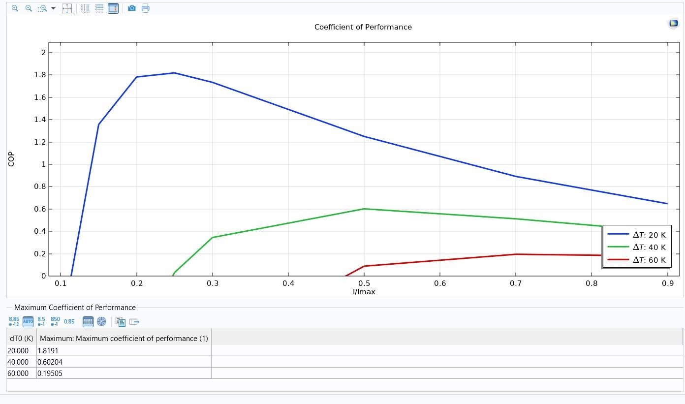
COMSOL was also used to look at a single TEC module on its own. The module's maximum temperature difference came out at 79 K, with a maximum current of 2.33 A. The COP depends strongly on how large a temperature difference the module has to hold, and it peaked at about 1.8 for a 20 K difference, about 0.6 for 40 K and about 0.2 for 60 K.
The electronics
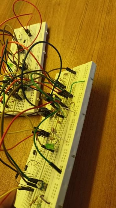
Each battery has its own charging and protection circuit, designed in Proteus. A 5 V supply feeds two LM317 regulators, one limiting the charging current and one setting the voltage, so the battery gets the right charge whatever the input. A TL431 reference diode, set with a potentiometer, decides when charging should stop. When it switches on, a PNP transistor bypasses the battery and sends the extra power into a string of diodes that act as a dummy load.
A PIC microcontroller runs the thermal control. It reads the battery temperatures and checks them against a 50 °C limit, runs the TECs for a fixed three seconds when a battery gets hot, and switches a battery off if it keeps heating. I assisted with this part of the work.
The prototype
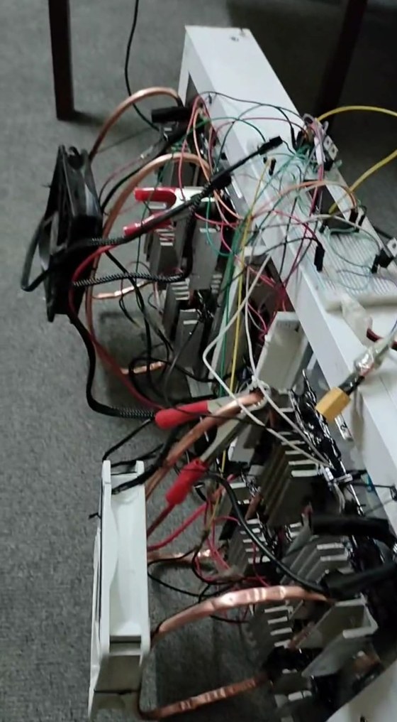
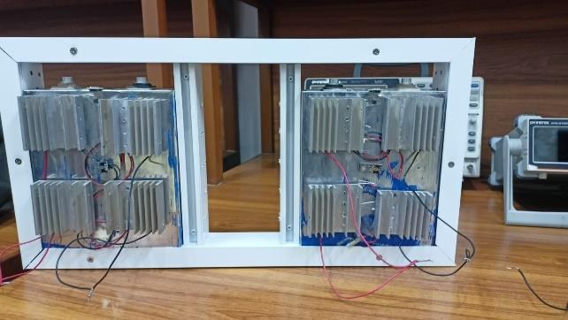
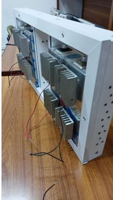
The prototype follows the same layout as the CAD model. A white frame holds the batteries, with TEC modules on the back of each one and a heat sink on every TEC. Building it from scratch meant making the frame, mounting the TECs and heat sinks on it, and wiring the circuit.
Results
In the thermal results, the batteries rose to 50 °C in running conditions and the casing to 38 °C, but along the TECs the temperature fell to 35 °C. The cold face of the TECs reached −10 °C and the hot face about 40 °C. The heat sinks and heat pipe rose to about 45 °C as they carried the heat away. The team's conclusion was that the TECs bring the battery operating temperature down from 50 °C to about 35 °C.
Across ten readings in the results table, the COP of the system ranged from 2.04 to 3.54, with the best values at the lowest cold side temperatures. For comparison, the report quotes COP values from published battery cooling research that range from 0.5 to 5. All of this was achieved without a refrigeration cycle or a water loop.
Takeaways
- The COP drops quickly as the temperature difference across the TEC grows, so removing heat from the hot side matters as much as cooling the cold side.
- Series and parallel wiring of the TECs is a real design choice, because it trades current against voltage to cut the power the TECs need.
- In the simulation the heat left the battery mainly under the TECs, so the placement of the TECs matters.
- The simulation fixed the TEC faces at set temperatures, so it shows the heat paths and not a full transient response of the battery.
Next
- Scale the prototype up for an electric vehicle or a photovoltaic battery bank, at 12 V to 48 V.
- Compare it against a conventional battery management system for cost and maintenance.